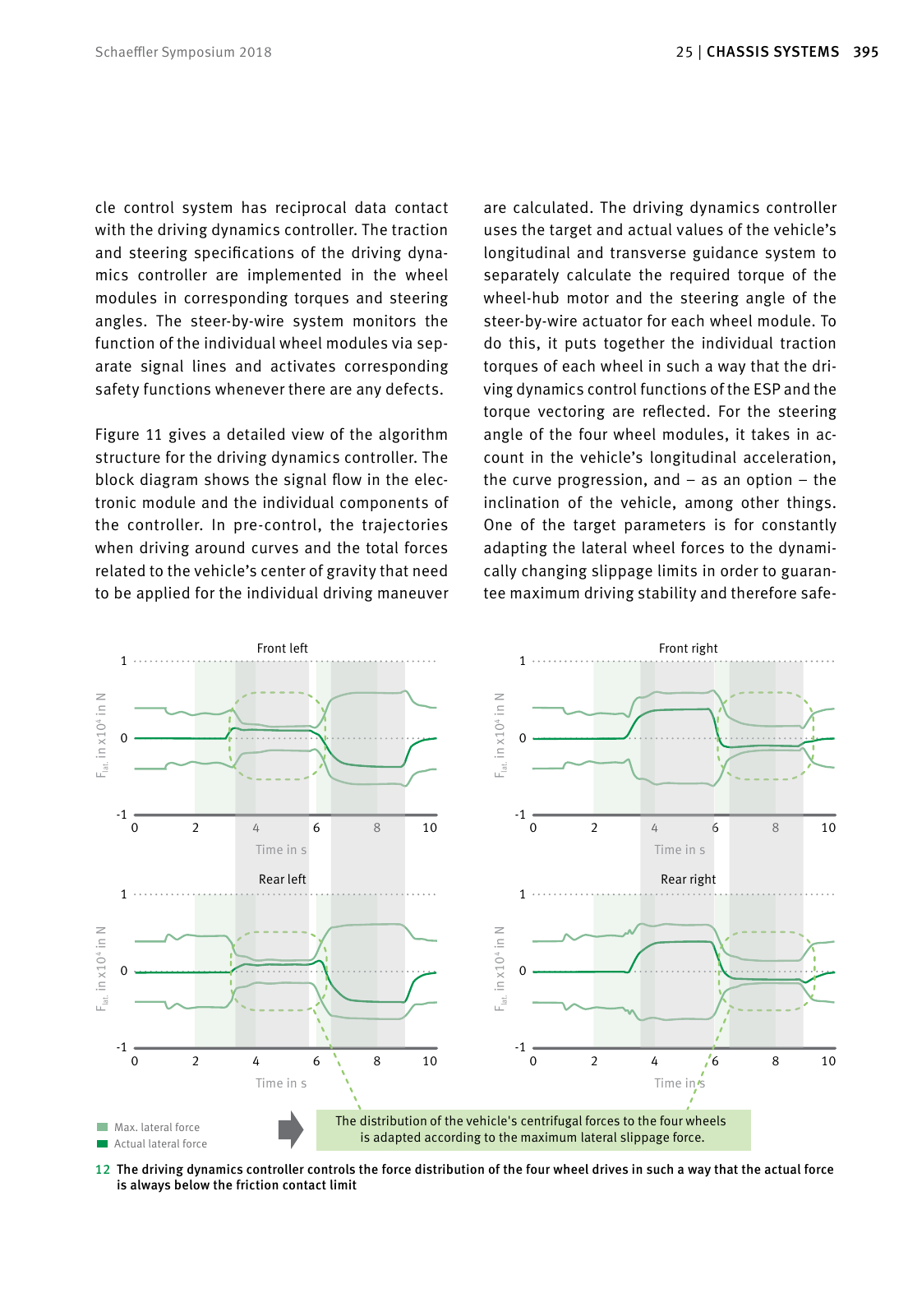
394 CHASSIS SYSTEMS 25 39525 CHASSIS SYSTEMSSchaeffler Symposium 2018 The control unit for the highly automated driving functions marked in red in Figure 10 above is directly connected with the controller for the com plete vehicle blue via a CAN bus Among other things this controls the braking and recuperation function along with comfort elements such as the air conditioner During the development and test phase a driver will be on board to monitor the driving function and intervene using a central joystick if necessary Later on in regular opera tion this module integrated via CAN bus 4 in Figure 10 will no longer be necessary The vehi cle control system has reciprocal data contact with the driving dynamics controller The traction and steering specifications of the driving dyna mics controller are implemented in the wheel modules in corresponding torques and steering angles The steer by wire system monitors the function of the individual wheel modules via sep arate signal lines and activates corresponding safety functions whenever there are any defects Figure 11 gives a detailed view of the algorithm structure for the driving dynamics controller The block diagram shows the signal flow in the elec tronic module and the individual components of the controller In pre control the trajectories when driving around curves and the total forces related to the vehicle s center of gravity that need to be applied for the individual driving maneuver are calculated The driving dynamics controller uses the target and actual values of the vehicle s longitudinal and transverse guidance system to separately calculate the required torque of the wheel hub motor and the steering angle of the steer by wire actuator for each wheel module To do this it puts together the individual traction torques of each wheel in such a way that the dri ving dynamics control functions of the ESP and the torque vectoring are reflected For the steering angle of the four wheel modules it takes in ac count in the vehicle s longitudinal acceleration the curve progression and as an option the inclination of the vehicle among other things One of the target parameters is for constantly adapting the lateral wheel forces to the dynami cally changing slippage limits in order to guaran tee maximum driving stability and therefore safe 10 Signal flows for controlling the wheel modules Dynamics control unit ECU steering FL ECU wheel drive FL ECU steering FR ECU wheel drive FR ECU steering RL ECU wheel drive RL ECU steering RR ECU wheel drive RR Corner modul FL Corner modul FR Corner modul RL Corner modul RR CAN 1 CAN 2 Inertial sensors L 5 Vehicle control unit HAD control CAN 4 CAN 7 Sensors CAN 6 Others Heating Climate control Door opener HMI Break actuator Batterie separator 48V 300V CAN 5 L 1 L 4L 2 L 3 yHS yH ZH Mω Mδ ω δ FHS FHR FHD Fxyd Target forces and yaw torque in the vehicle s center of gravity Target forces at the wheels Control of the horizontal vehicle dynamics Target forces at the wheels Provides stabilization Fe ed fo rw ar d co nt ro l Ve hi cl e Single wheel feedback control Provides ASR and ABS Wheel forces assignment Provides 4x target steering angle 4x target wheel drive torque 11 Signal flow in the electronic module and the individual components of the controller 0 2 4 6 8 10 0 1 1 0 2 4 6 8 10 0 1 1 0 2 4 6 8 10 0 1 1 0 2 4 6 8 10 0 1 1 Max lateral force Actual lateral force The distribution of the vehicle s centrifugal forces to the four wheels is adapted according to the maximum lateral slippage force F la t in x 10 4 i n N Time in s F la t in x 10 4 i n N Time in s F la t in x 10 4 i n N Time in s F la t in x 10 4 i n N Time in s Front left Rear left Front right Rear right 12 The driving dynamics controller controls the force distribution of the four wheel drives in such a way that the actual force is always below the friction contact limit
Hinweis: Dies ist eine maschinenlesbare No-Flash Ansicht.
Klicken Sie hier um zur Online-Version zu gelangen.
Klicken Sie hier um zur Online-Version zu gelangen.